The purpose of aerodynamic testing is to assess and compare aerodynamic characteristics and performance.
Whether in a windtunnel, velodrome, or on the road, organisation and precision are of the utmost importance.
The CIRRUS portal uses a test structure with a basic hierarchy.
Session: a collection of configs, taken on the same day with the same rider, which can all be compared.
Configs: a collection of runs which should have the same performance values.
Runs: a logging period comprised of a collection of consecutive traverses/laps, with continous data logging.
Traverses/Laps: a section of relevant data within a run, demarcated by gates or lap markers.
This structure simplifies the organisation of the test, and ensures that the equipment and underlying performance
calculations are applied in the appropriate manner.
Until one establishes a certain level of expertise and understanding, we strongly recommend that all tests use this
session structure. It will result in a vastly more coherent and rewarding user experience.
Portal Set Up
Intro
Login into the portal using the credential you received via email.
Rider and default calibration are only needed when adding a new rider.
If the rider already exists in the system, skip to 'Sessions'.
Riders
Create new or select existing rider
To create a new rider select the 'RIDERS' tab, then select
Nickname is mandatory and must be unique within the team, display name will be created automatically
Input the approximate mass of the rider without the bicycle (+/- 3 kg)
The precise combined mass of rider and bicycle for the calculation will be entered later
Save
Test Creation
Sessions
To create a session select the 'SESSIONS' tab, then select 'New Session'
Input session type - typically 'Transverse Aero Test'
Select test type (rider or equipment)
Select date, rider and alter description where required
Calibration
Check Combined Mass and CRR
Save
Configs
Add configurations to the sessions:
Select the desired session
To add configurations, select 'Edit > New Config'
Add the number of planned runs for each configuration using
Configs and runs can be added while testing or afterwards. However, testing is easier if a basic test plan is created beforehand.
Configs & Runs During Testing
Baseline configuration will be automatically selected for the first run.
The server will always automatically populate the next available run in sequential order. The symbol denotes the next run to be populated.
For example, if the first 2 out of your 3 runs on configuration 'A' have been populated and you now select configuration 'B', the next run to be populated will be the first run on configuration 'B'. This run will be automatically assigned run number '3'.
Other configs can be selected by pressing and highlighting while 'CONFG LIST' is selected. This can be done easily on a mobile phone during testing.
To edit the order of runs, you can alternatively select 'RUN LIST' then .
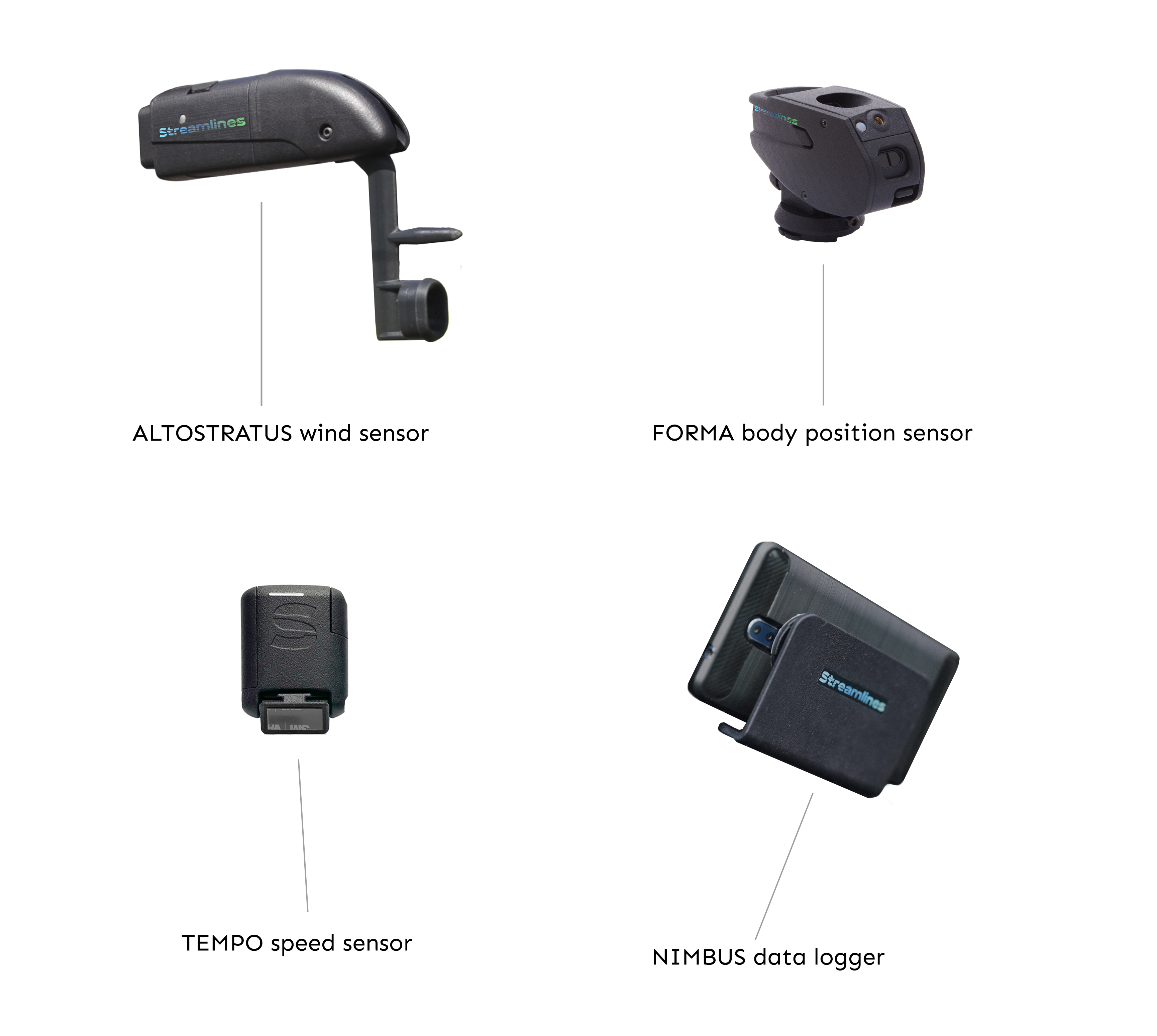
NIMBUS App
The NIMBUS App comes installed in the data logger device.
Turn on the data logger phone supplied. Ensure data connection is enabled.
Start the NIMBUS app
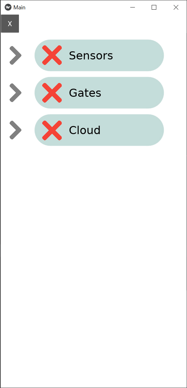
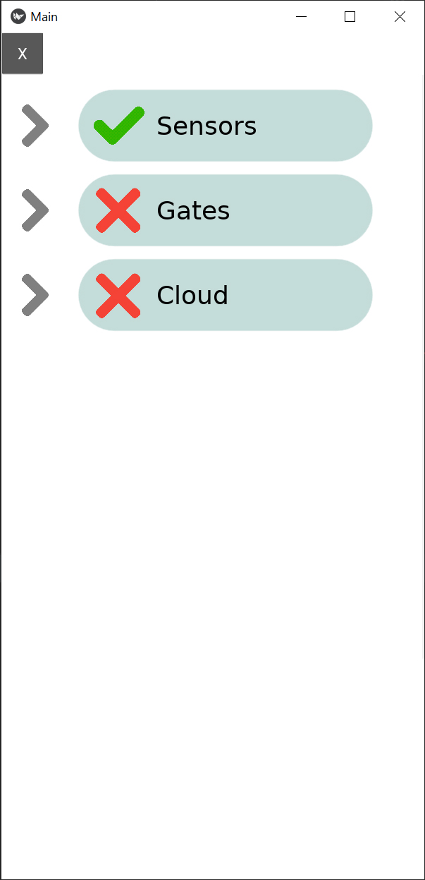
On the start up screen, go to Setup
Expand the Sensors section
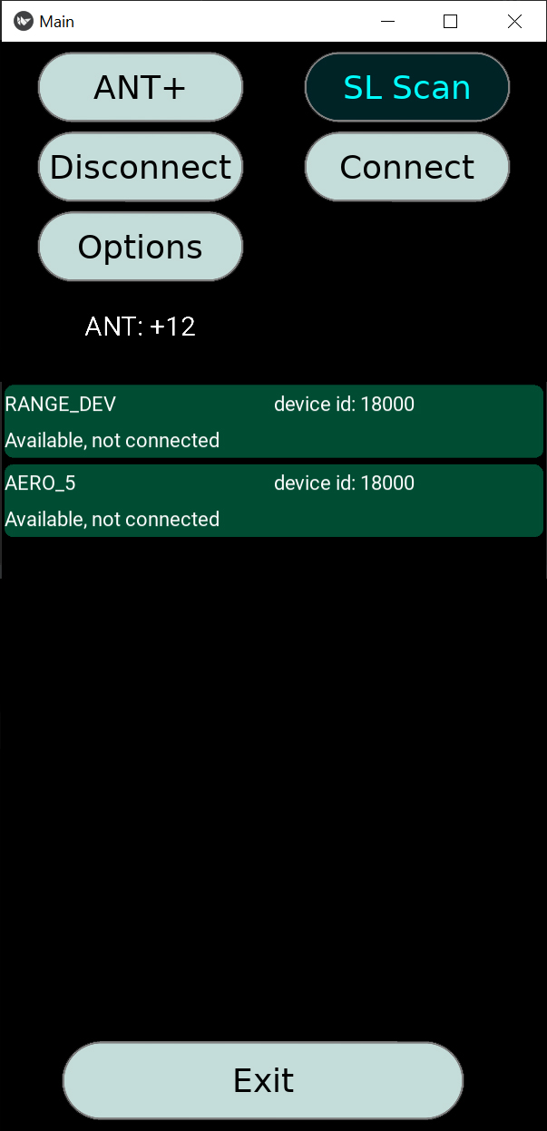
Select Connections
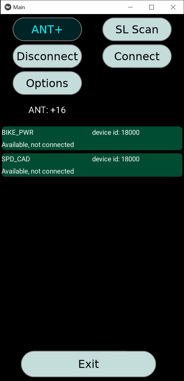
To connect the power meter and speed sensors, press ANT+
After devices appear, select each one and press Connect
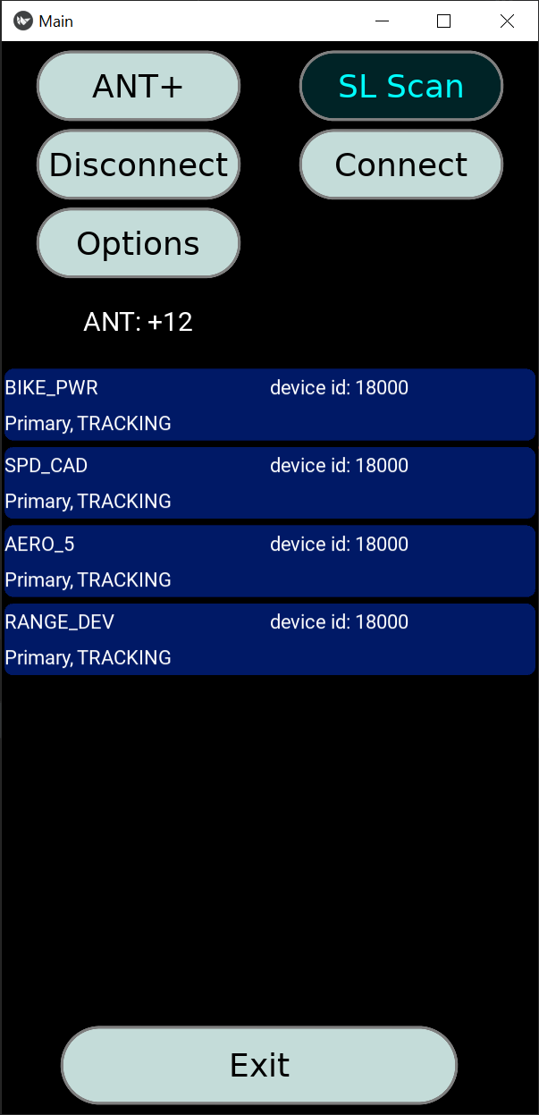
To connect the wind and body position sensors, press SL Scan
After devices appear, select each sensor and press Connect
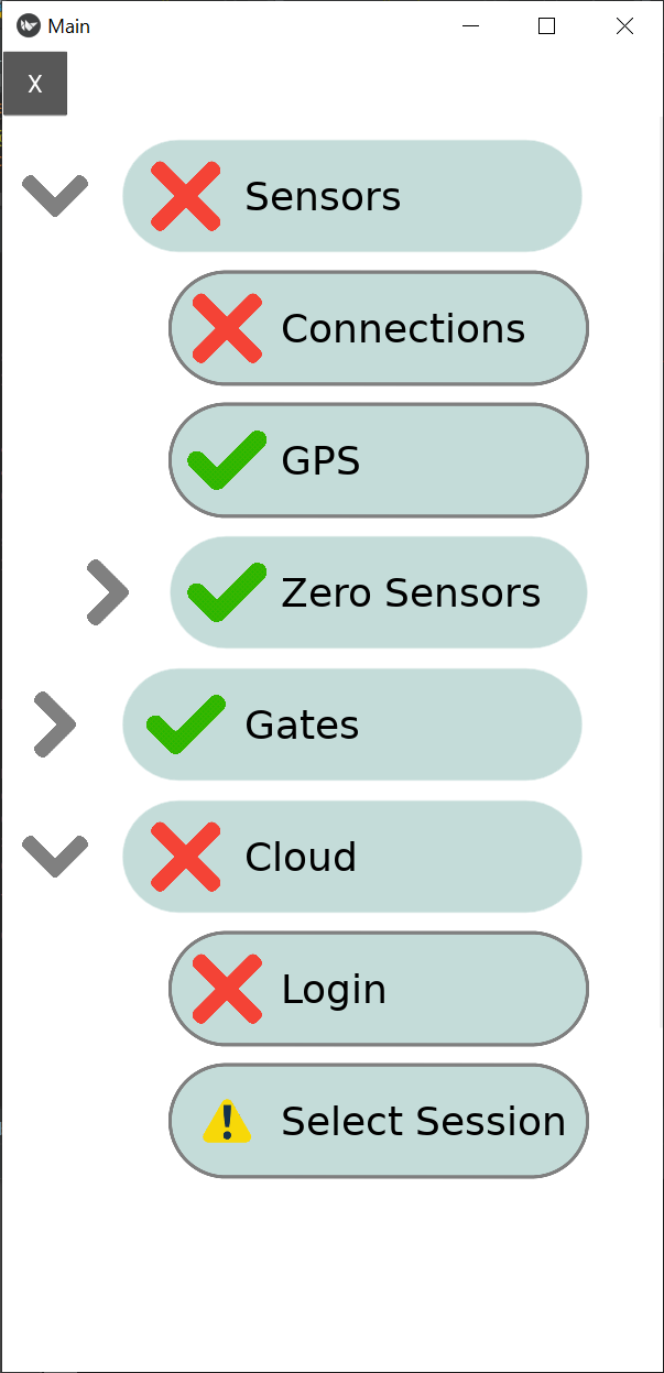
All sensors should now show as 'TRACKING'
IMPORTANT: When connecting sensors in a busy test environment, with multiple devices present, ensure you are connecting
to the correct sensors by verifying the unique ID of each sensor.
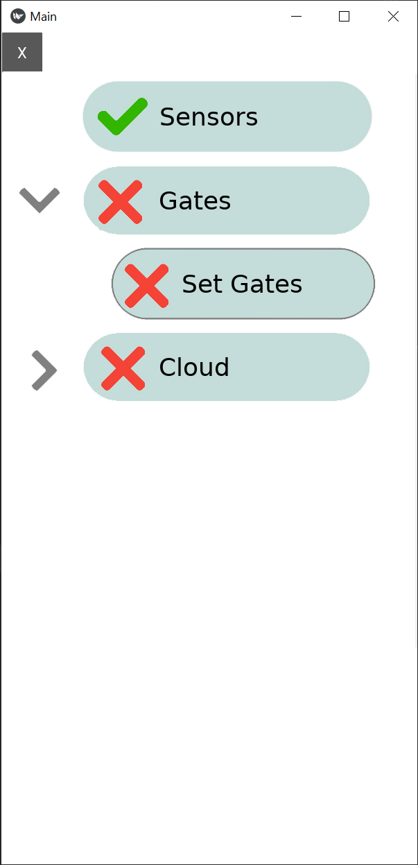
If all the sensors have been successfully connected, the Setup
screen should now show a next to Sensors
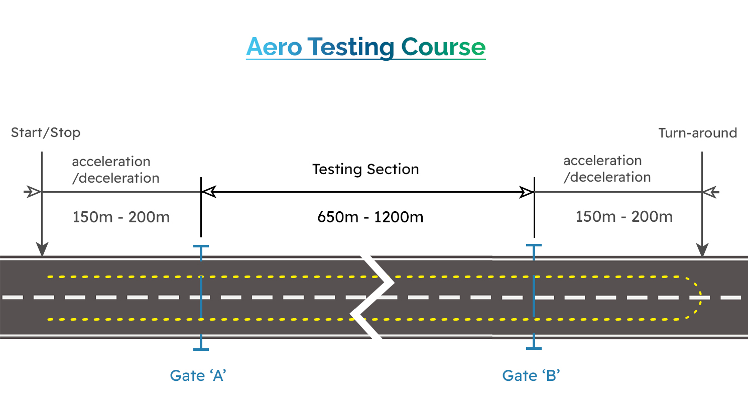
Courses and Gates
Course layout should be similar to the one on the diagram below
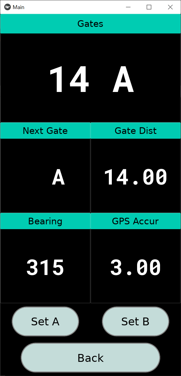
Mark the Gates
Find suitable spot for gate 'A'
On the NIMBUS app start screen, select Setup
In the next screen, expand the Gates section, then select Set Gates
'Set A' while at gate 'A'
Repeat process for gate 'B'
Please note that the order in which you mark the gates is not important. Rider can start course at gate 'B' if desired.
Zeroing the Sensors
Zero the power meter using a suitable head unit
Zero the wind sensor using the NIMBUS app
Display Main Menu> Other Displays> Wind Sensor
Shield, but do not block, sensor ports with hand or body (if outside)
Press Measure
Press Apply
Diff1, Diff2 & Diff3 pressure readings on right-hand column should read between 0 and 1
Performing Tests
Start NUMBUS app (see NIMBUS app section)
Ensure sensors are connected and zeroed
Ensure sensors are working as expected by going to Setup > Sensors > Response and then checking the individual sensors for a sensible reading
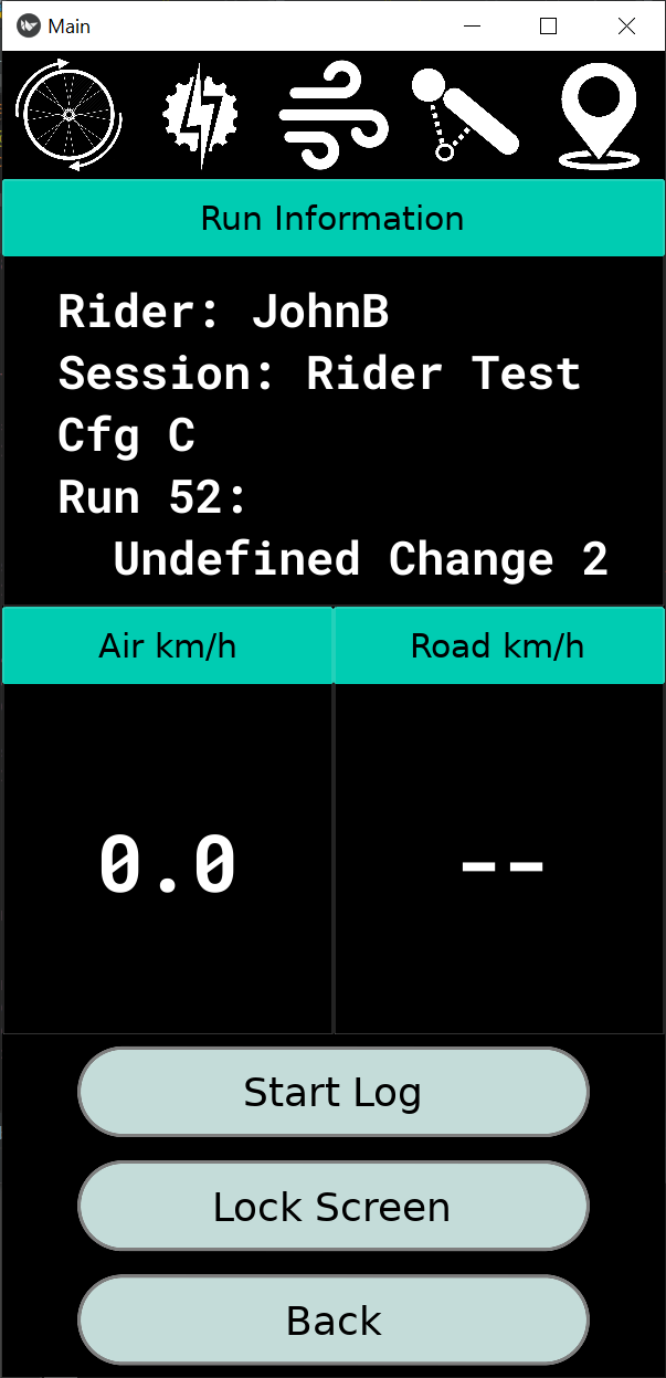
Your test will be displayed under Run Information on the test screen
On the start screen go to Test, then press
Start Log to start logging your test. The screen will automatically lock when you start logging.
Ride at constant power through gates 'A' to 'B' and return 'B' to 'A'.
You can press the Lock Screen button to ensure you don't
accidentally press any buttons during testing. To unlock the screen, press the
Lock Screen button 3 times in quick succession.
Important Safety Information
WARNINGS:
Pay attention to your surroundings and use your best judgement to ensure you always operate the bicycle safely.
Before turning around after completing a traverse, we strongly recommend that the rider comes to a complete stop and ensures that no vehicles are behind them.
Your bicycle and hardware should be properly installed and maintained at all times.
The use of LED lights is always recommended during testing.

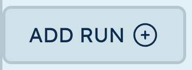
 denotes the next run to be populated.
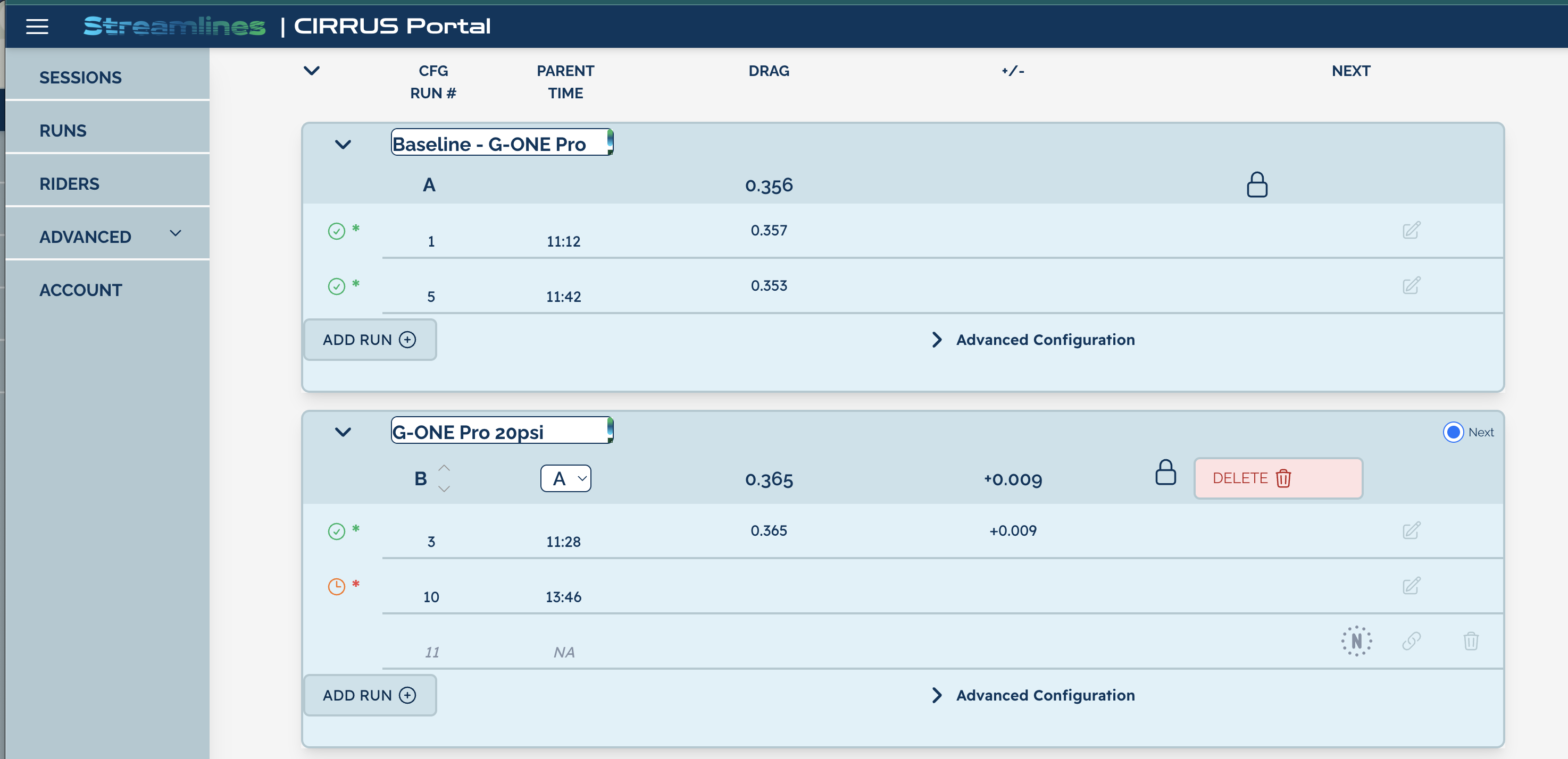
 and highlighting
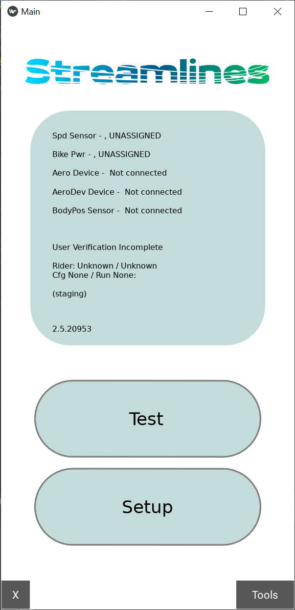
 WARNINGS: